Bending of CFR thermoplastic tubular structures
Abstract
This paper describes the practices for bending tubular structures made from continuous fiber-reinforced thermoplastics. The described method was specifically tested on tubes manufactured with the AFP process of laser-assisted tape winding technology (LATW). The described basic practices aim to achieve postforming of tubular structures without critical defects such as folds, wrinkles, and fiber damage, while improving the external surface quality. The objective of this research is to demonstrate successful post-forming of high-quality CFR Thermoplastic shapes at low cost and to develop automatable practices, enabling a wide range of applications for diversified products and markets. The article aims to encourage and enable more people to explore this new technology and develop additional opportunities for reshaped tubular structures.
The following work has been conducted within the AFPT Group, consisting of the AFPT GmbH (responsible for the development of process technology and sale of production equipment) and Alformet (GmbH & BV, responsible for development of CFR TP parts and their production).
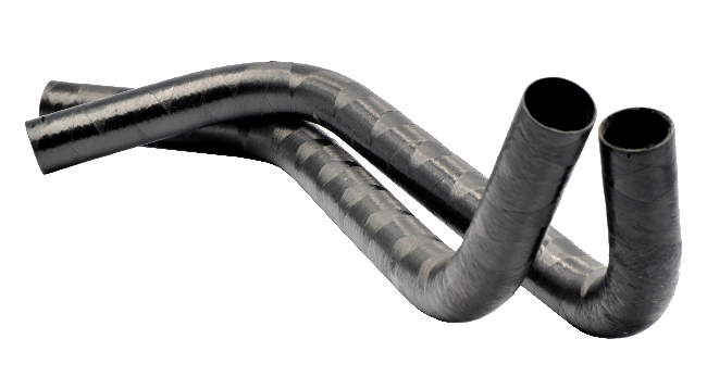
Figure 1: Bent CFR TP tube (PP-CF)
Introduction
FRP-based products are gaining importance in many markets due to their low specific weight, high specific strength/stiffness ratio, corrosion resistance, and chemical resistance. For instance, manufacturers in the automotive market can reduce weight and energy consumption of a car while improving performance. FRP-based products can be divided into two major groups: fiber-reinforced thermosets and thermoplastics. Thermosets are irreversibly chemically formed and have limited recyclability. Fiber-reinforced thermoplastics (FRTP) have specific characteristics compared to fiber-reinforced thermosets, including damping properties, chemical resistance, hot-forming capability, (easy) recyclability, and more.
The application of thermoplastic-based UD-tapes in the so-called Automated Fiber Placement (AFP) processes has enabled a high level of automation, high productivity, and well-controlled processes. Laser Assisted Tape Winding (LATW) is an example of such technologies that allow a wide range of applications, from fast prototyping to large series production with strict process control. LATW technology used to manufacture short, long, and endless tubes that can be further processed. Post-processing of the tubes (round and non-round) is possible, similar to metals through machining, bending, and welding. This article focuses on the post-forming of straight tubes using high-temperature forming, providing insights into the current practices.
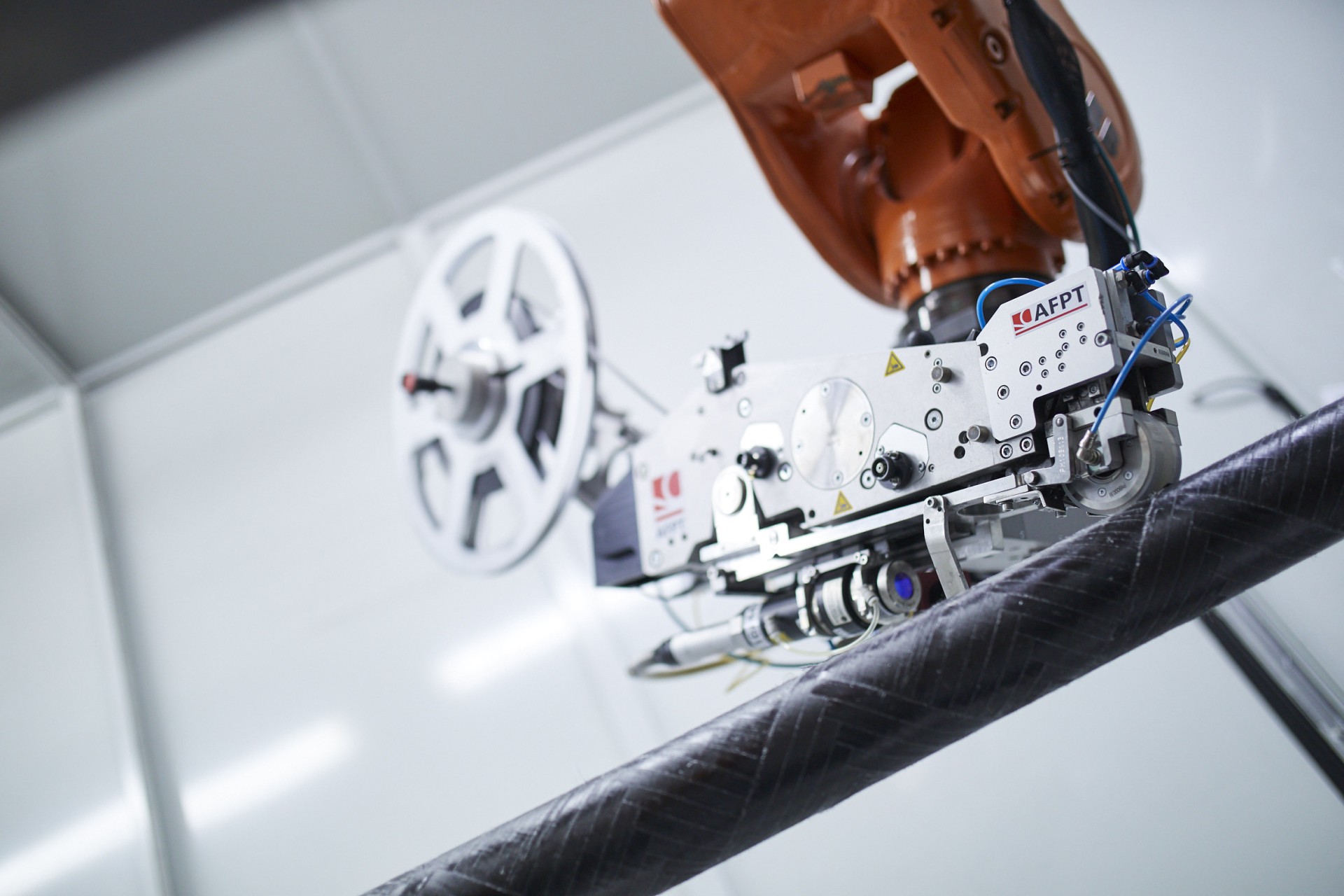
Figure 2: The laser equipment (courtesy of AFPT)
Practices for Bending CFR Thermoplastic (CFR TP) Tubes
Under post-forming, several operations can be grouped, such as bending and cross-section reforming. This paper focuses on bending round tubes. The ability to post-form CFR thermoplastic tubes in bending is quite similar to metal bending technology. However, the behavior of the material is different and affects the specific methodology to obtain the best results. It is important to understand the effect and behavior of the fibers within the thermoplastic matrix before and during the post-forming process. The principal behavior of the fibers within the thermoplastic matrix is described in an publication called "Fiber Angle Prediction for Post-Forming of Carbon Fiber-Reinforced Composite Tubular Structures" by Li et al.
In summary, this article describes how the fibers in the layers of a CFR thermoplastic tube reposition during the bending operation and how this repositioning can be predicted using a mathematical formula. The adapted fiber angle varies and depends on the position in the bending zone, becoming larger on the inner bending radius area and smaller on the outer bending radius. Althrough cross-section reforming isn't the focus of this article, a study about how the fiber angle changes in that method can be found in a publication called "End-forming of Continuous Fibre-reinforced Thermoplastic Tubes" by Reuter et al.
In the shown pictures of the fiber angles, the straight tube was wound with a ±41° cross-winding laminate. After bending the 90-degree curve, the theoretical fiber angles calculated with the formulas presented in the aforementioned article are 27.4 degrees and 51.0 degrees, respectively. These numbers deviate somewhat from the angles measured in our case and presented in the pictures. An explanation for the difference could be found in the fact that the thermoplastic matrix, especially its viscosity, will have a damping effect on the repositioning of the fibers and will result in a slight deformation of the round shape. As a result, the fiber angle will not reach the theoretical values calculated and will fall short. Another aspect that plays a role in the actual fiber angles is the fact that the length of the fibers remains the same during the bending process, meaning inside and outside fiber angles are closely related.
With this scientific knowledge in mind, a number of findings and practices for successful bending of CFR thermoplastic tubes can be presented. Starting with the sequence of process steps for post-forming CFR thermoplastic tubular structures, we specify the following steps and further describe them:
- Assemble internal and external support of the tube.
- Heat of the material above the melting temperature of the thermoplastic matrix.
- Bend the assembly.
- Cool the assembly.
- Remove supports.
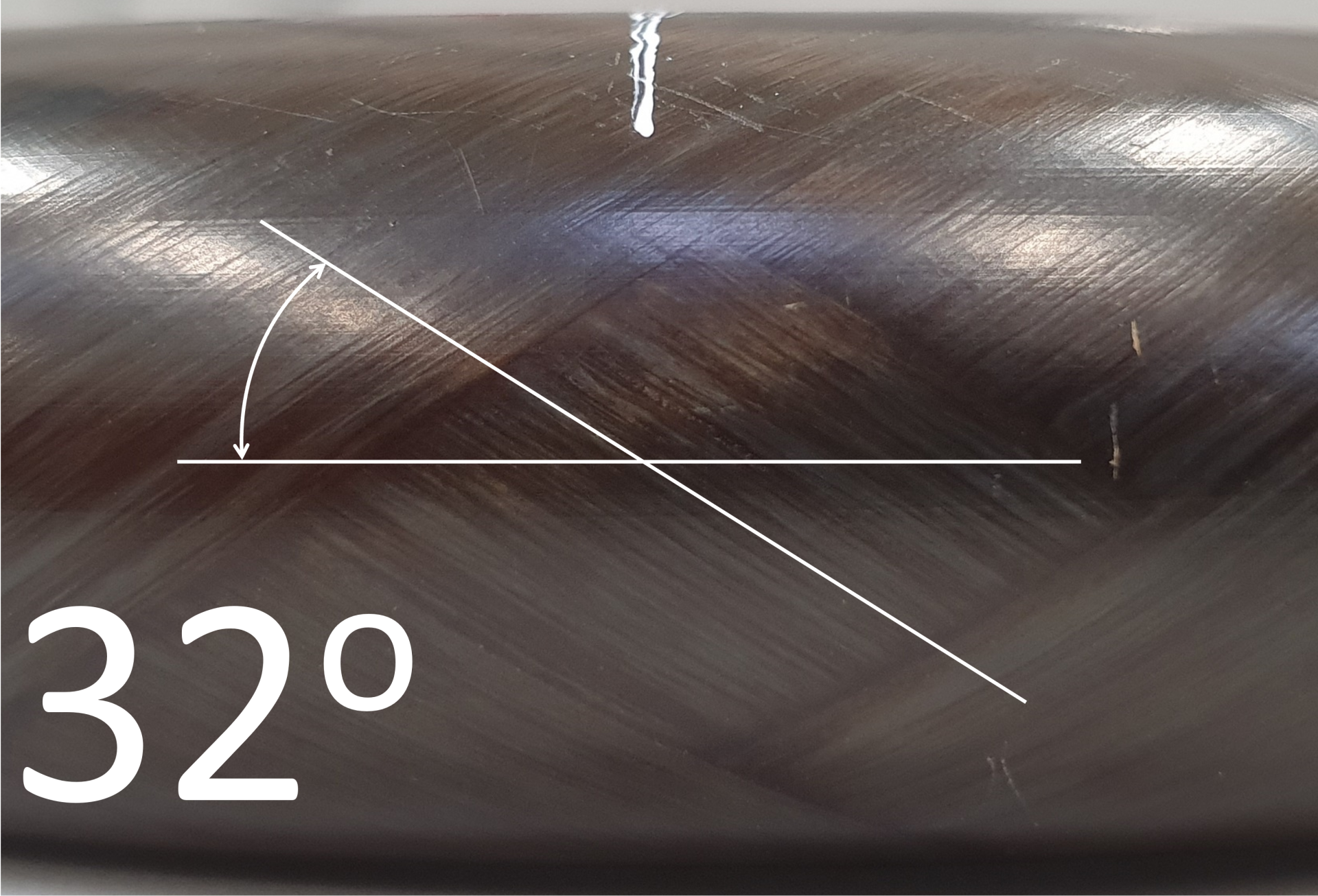
Figure 3.1: Fiber angle at the outer radius of a tube bent 90°
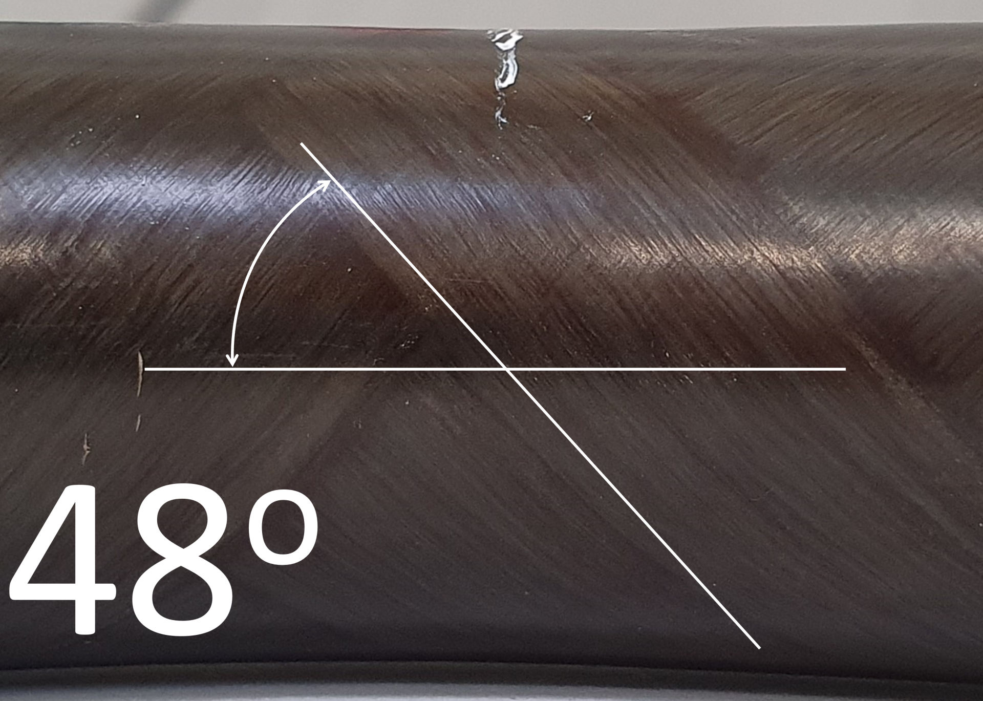
Figure 3.2: Fiber angle at the inner radius of a tube bent 90°
1. Assemble internal and external support of the tube
An important difference compared to metal bending is that the bending process must be executed when the thermoplastic matrix is in a soft state. In other words, the temperature of the material generally needs to be above the melting temperature of the thermoplastic material. In this state, the shape can be altered without applying high forces, however it is also vulnerable to unintended changes. Specifically, when bending a shape, buckling of the CFR TP tube can occur if the material cannot withstand the compressive forces on the inner bending radius. To control this effect and prevent buckling during the bending process, both the inner and outer parts of the tube need to be supported.
The inner part of the tube is supported with sand, which combines the ability to be reshaped (flexible) and to resist compression. It is essential to cap both ends and enclose the sand inside the CFR thermoplastic tube to maintain its strengthening task and prevent tube buckling. Additionally, an internal silicon protection, either in the form of a hose or sheet material, prevents sand particles from sticking to the inner tube wall. Alternative materials for the internal support, such as silicon or compressed air, can be used instead of sand, but sand offers a perfect combination of high flexibility and low compressibility.
On the outer part of the tube, a silicon hose is used to create a compressive pressure around the circumference of the CFR TP tube. The inner diameter of the silicon hose is approximately 25% smaller than the outer diameter of the CFR TP tube to achieve the compressive force. In addition to preventing buckling, the compressive force applied by the silicon hose during tube heating results in a smooth outer surface after melting of the thermoplastic matrix. Both sand and silicon can withstand the temperatures reached during the heating process for the chosen materials.
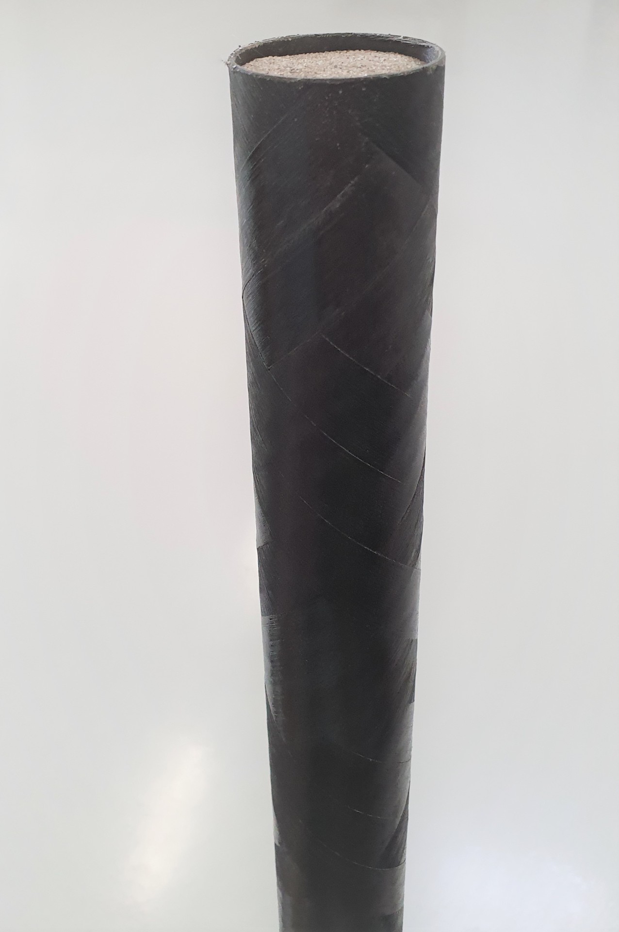
Figure 4: CFR TP tube filled with sand
Figure 5: Silicon hose placed around the CFR-TP tube
2. Heat of the assembly above the melting temperature of the thermoplastic matrix
This process step, required to reshape/bend the tube, can be achieved by heating the bending zone region or by completely heating the assembly in an oven. The temperature and duration of the heating process depend on the thermoplastic material's melt temperature, the size of the assembly (or volume of the heated tube or tube part), and the capacity of the heating device used.
After the heating process is completed, the material becomes more vulnerable and needs to be handled with care. The vulnerability depends on factors such as the thermoplastic material used (viscosity), wall thickness (number of layers), heating temperature, and the shape of the mold used in relation to the required final shape.
As previously mentioend, a side effect of using the silicon hose is the smooth surface obtained by applying a compressive force on the outer surface of the tube during heating around the melt temperature of the thermoplastic matrix, as can been seen in picture.
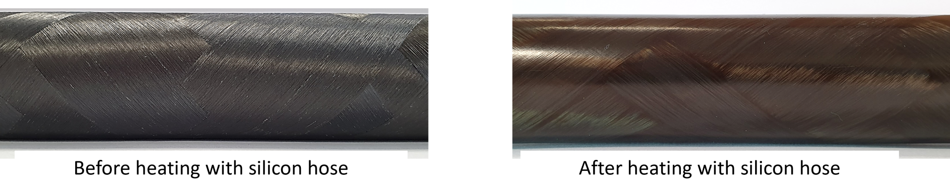
Figure 6: Outer surface before and after heating using a silicon hose
3. Bend the assembly
After the heating process, the CFR thermoplastic tube is ready for reshaping/bending. Generally, manual bending is possible as it requires only a small force. However, a mold can be used to achieve a predefined shape and ensure accurate repeatability of the bending process for multiple products. A half shell mold is usually sufficient, and the design of the mold should compensate for possible spring-back effects after cooling and releasing the bent tube. The spring-back effect varies depending on factors such as the material used, winding angle applied, bending radius/angle, and wall thickness of the tube.
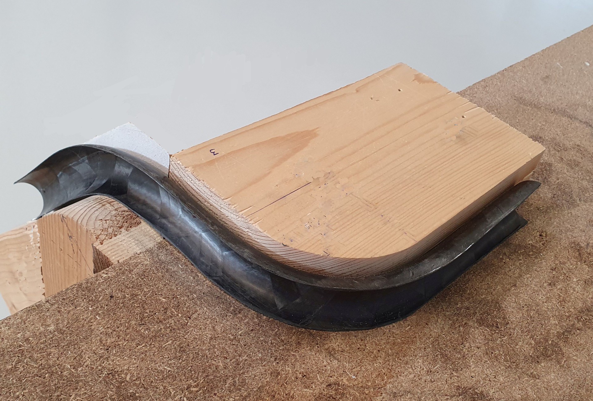
Figure 7: Half shell mold made by cutting a larger tube along its axis
4. Cool the assembly
By allowing natural or forced cooling, the temperature of the bent tube will decrease to ambient level. Once the temperature is below the glass transitional temperature of the thermoplastic matrix, the risk of shape changes or material damage becomes very small. A fan is sufficient to reduce the tube's temperature relatively quickly, otherwise, water can also be used.
5. Remove the supports
After cooling the object, the silicon hose can be removed, followed by the plugs and the sand. All these materials (silicon hose, plugs, and sand) can be saved and reused. The two ends of the tube may show some deformation due to the plugs and will need to be cut off. The bent tube is now ready for use.
_20230724110208993.jpg)
Figure 8: A 25mm CFR TP tube bent in S-shape (PC-CF heated 45 min. at 225°C)
Takeaways for Optimising Quality
From all the trials conducted at our companies, several findings can be shared:
- The main objective of the described process is to achieve a bent shape without defects. The main defect that can occur is wrinkles appearing on the inner bending radius of the tube. These wrinkles not only have an aesthetic issue but also have a significant impact on the strength and stiffness. The undulated fibers in the wrinkled area do not effectively contribute to the tube's reinforcement.
- If the sand (or any other medium) inside the CFR TP tube cannot build up enough resistance/counterforces during the bending process, the likelihood of forming wrinkles is very high.
- The compressive force applied by the silicon hose on the outside of the tube contributes to prevent wrinkles during the bending process.
- The silicon hose has additional functions apart from preventing wrinkles. It protects the thermoplastic matrix from oxidation during the heating process and creates a smooth surface on the outside of the wound CFR TP tube.
- Silicon hose material is commercially available in various diameters, hardness levels and temperature resistance levels, depending on individual needs.
- The heating-and-cooling cycle of the bending zone is important for the end result. A faster heating cycle increases productivity with lower costs. However, a cycle time that is too short increases the likelihood of wrinkles and does not result in a perfect outer surface quality. The dissipation of heat by the medium inside the tube (sand) must be taken into account when determining the duration of the total cycle time. In our hot air circulation oven, the typical heating time for a 25 mm internal diameter tube filled with sand is around 45 minutes, and for a 30 mm inner diameter, it is around 60 minutes. The temperature depends on the material used.
- The materials tested with this process so far include:
- PP (heated at 200°C),
- PA6 (heated at 230°C),
- PA12 (heated at 210°C),
- PC (heated at 225°C),
- All composites so far were carbon fiber reinforced and yielded successful bending results. By the usage of glass fibers, an increased spring-back effect is to be expected. After fine-tuning for the thermal expansion, there is no reason to expect the results to be any less successful.
- The winding angle of the UD-tape in each layer of the CFR TP tube has an influence on the ability to bend CFR TP tubes without wrinkles. A typical range between 30 and 60 degrees provides good bending results along with the desired stiffness of the final shape. The thermoplastic matrix also plays an important role, and the viscosity of the thermoplastic matrix during bending is crucial for the mobility and repositioning of the fibers.
- The effect of the heating and cooling process on the properties of the thermoplastic matrix was not within the scope of this work. The full effect is unknown, but results show that porosity is reduced in the heating cycle, which is positive for the mechanical properties. The effect of the heating and cooling cycle is expected to vary depending on the type of thermoplastics (amorphous versus semi-crystalline) and the cooling rate.
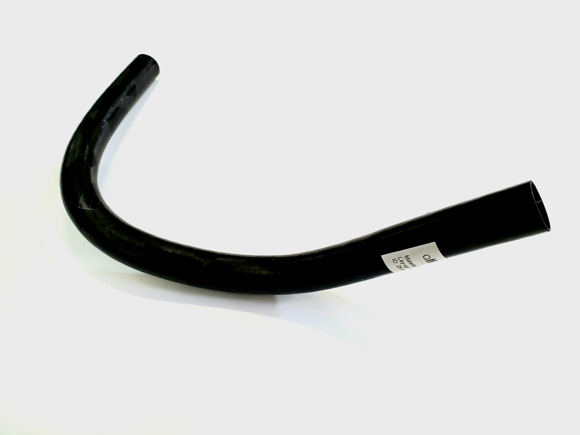
Figure 9: A 25 mm CFR TP tube bent in two planes: 90° and 45° curves (PA6-CF heated 45 min. at 235°C)
Conclusion
FRTP composite parts have a huge potential due to their high strength and stiffness, lightweight, recyclability and low maintenance. The ability to reshape and bend such parts, which can be achieved with limited investment in equipment and materials, also opens up new applications. For example, in construction elements, reshaped/bent CFRTP tubes can replace separate connector elements (e.g., bolts/nuts), saving time and cost in the assembly of furniture parts (e.g., chair base elements), poles in buses and trains, bicycle structures high pressure hoses and connectors. Even further expansion is possible by exploring local reshaping not only in tubes but in other CFRTP products.
AFPT and Alformet have developed significant knowledge in how to execute the bending/reshaping process and is also exploring further development by automation and fine-tuning of the steps described here. AFPT Group invites interested parties to collaborate in continuing this development. Please contact info@alformet.de.
Written by Theo Mimpen and Florian Henne (February 2023)